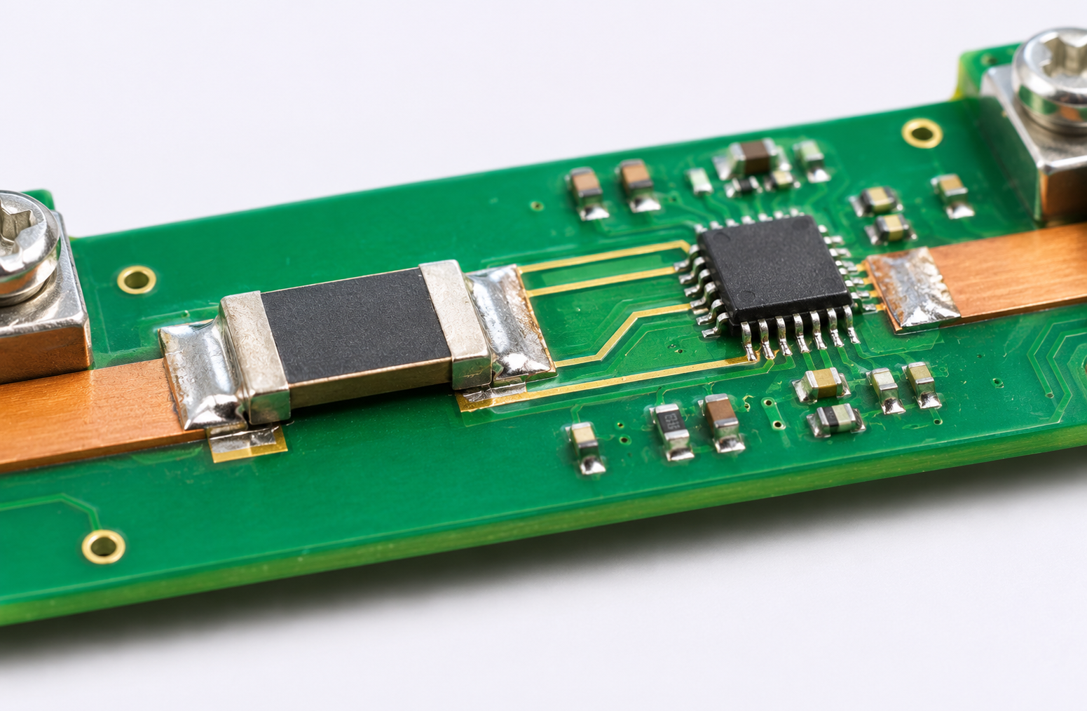
How to Choose a Shunt Resistor for the INA226
The INA226 is one of the most accurate current and power monitors you can put on an I2C bus. It has a 16-bit converter, a maximum gain error of 0.1 percent and an input offset of only 10 microvolts. None of that helps if the resistor it measures across is the wrong value, the wrong type or badly connected. In practice, the shunt resistor and its layout decide the accuracy of the whole measurement far more often than the chip does.
This guide explains how to choose that resistor. It covers the trade-off at the heart of the decision, works through a complete example with numbers, and then deals with tolerance, temperature drift, package and layout. By the end you will be able to pick a shunt for any current range and program the INA226 to match.
What the shunt does
A shunt is a low-value resistor placed in series with the load. Current flowing through it produces a small voltage, equal to the current multiplied by the resistance. The INA226 measures that voltage differentially between its two input pins and converts it to a number.
Two facts about the INA226 input set the boundaries for the design.
- Full-scale range:plus or minus 81.92 mV. Shunt voltages beyond this cannot be measured.
- Step size:5 microvolts. This is the smallest change in shunt voltage the converter reports.
Unlike some older monitors, the INA226 has a single fixed input range, so there is no gain setting to choose. Everything is controlled by the resistor value.
The central trade-off
A larger resistance produces a larger voltage for the same current. That gives finer current resolution and makes the chip’s small offset less significant, so low-current readings are more accurate.
A larger resistance also wastes more power, drops more voltage in series with the load, and heats up more, which shifts its value.
A smaller resistance does the opposite: less loss and less heating, but coarser resolution and more sensitivity to offset and noise.
The task is to find the largest value that stays inside the 81.92 mV input range at maximum current and keeps the voltage drop and power loss acceptable.
Step 1: Define the current range
Write down three numbers.
- Maximum currentyou need to measure, including any short peaks you care about.
- Minimum currentyou want to resolve meaningfully.
- Whether current flows in both directions.The INA226 reports signed values, so it handles charge and discharge without any change to the circuit.
For the worked example, take a 12 V system with a maximum of 10 A and a requirement to see changes of a few milliamps.
Step 2: Calculate the maximum resistance
The shunt voltage at maximum current must not exceed the full-scale range. Divide the full-scale voltage by the maximum current.
81.92 mV divided by 10 A is 8.192 milliohms.
That is the upper limit. It is wise to leave headroom for transients and for tolerance, so aim for a shunt voltage of 50 to 75 mV at maximum current. For 10 A, standard values of 5 milliohms and 7.5 milliohms fall in that band.
Step 3: Check the power and the voltage drop
Power dissipated in the shunt is the current squared times the resistance.
| Shunt value | Voltage at 10 A | Power at 10 A | Current per 2.5 microvolt step |
| 2 milliohms | 20 mV | 0.2 W | 1.25 mA |
| 5 milliohms | 50 mV | 0.5 W | 0.5 mA |
| 7.5 milliohms | 75 mV | 0.75 W | 0.33 mA |
| 8 milliohms | 80 mV | 0.8 W | 0.31 mA |
A 5 milliohm shunt loses half a watt at full load and drops 50 mV, which is 0.4 percent of a 12 V supply. That is a reasonable compromise. The 7.5 milliohm option gives finer resolution at the cost of half as much loss again. The 2 milliohm option runs cool but gives up resolution.
Take 5 milliohms for the example.
Step 4: Choose the power rating
Do not run a resistor at its rated power. A shunt at full rating can be 50 degrees or more above the board temperature, and its resistance shifts with that heat. A common rule is to keep dissipation at or below half the rated power at maximum current.
For 0.5 W of dissipation, choose a resistor rated for at least 1 W. A 2 W part will run cooler and drift less. Check the derating curve in the resistor datasheet as well, since the rated power falls at high ambient temperatures.
Step 5: Check the resolution and the low end
With 5 milliohms, each 2.5 microvolt step is 0.5 mA. That meets the requirement of seeing changes of a few milliamps.
Now check the effect of offset. The INA226’s maximum offset of 10 microvolts across 5 milliohms corresponds to 2 mA. So readings below a few milliamps are dominated by offset error, even though the display changes in 0.5 mA steps. If you need accurate readings at 1 mA, a 10 A range on a single shunt is asking too much, and you would need a larger shunt with a lower maximum current, or two measurement ranges.
This is the key point about dynamic range. As a rough guide, the INA226 gives useful accuracy over about three to four decades of current on one shunt.
Step 6: Program the calibration register
The INA226 can calculate current and power internally once you tell it about the shunt. This takes two steps.
Choose a current step. The current register is a signed 16-bit value, so the smallest usable step is the maximum current divided by 32,768. For 10 A that is about 305 microamps. It is convenient to round up to a tidy number. Choose 0.5 mA, which gives a full-scale reading of 16.38 A.
Calculate the calibration value. The datasheet formula is 0.00512 divided by the product of the current step and the shunt resistance.
0.00512 divided by (0.0005 A times 0.005 ohm) equals 2,048.
Write 2,048 to the calibration register. The current register then reads in units of 0.5 mA. The power register reads in units of 25 times the current step, which is 12.5 mW.
The calibration register is also a convenient place to trim out error. If a reference meter shows that your reading is 0.4 percent high, scale the calibration value by the same proportion to correct it.
Tolerance
The shunt’s tolerance adds directly to the measurement error. A 1 percent resistor makes the system no better than 1 percent, however good the chip is. To take advantage of the INA226’s 0.1 percent gain error, use a 0.5 percent or 0.1 percent shunt, or calibrate each unit in production against a known current and store a correction.
Calibration removes the initial tolerance but not drift, which is the next concern.
Temperature coefficient
Resistance changes with temperature. The temperature coefficient of resistance, given in parts per million per degree Celsius, tells you how much. A shunt with a coefficient of 200 parts per million per degree that warms by 50 degrees changes by 1 percent. One with 50 parts per million per degree changes by 0.25 percent.
Low-value resistors are more affected than you might expect, because the copper terminations make up a meaningful part of the total resistance, and copper has a very high temperature coefficient of about 3,900 parts per million per degree. Good current-sense resistors are built from metal alloy elements with low coefficients, and the best are four-terminal types that keep the terminations out of the measurement.
For precision work, choose a metal-element shunt with a coefficient of 75 parts per million per degree or lower, and oversize its power rating to limit self-heating.
Resistor type and package
- Thick-film chip resistorsare cheap and fine for rough monitoring. Their temperature coefficient and long-term stability are modest.
- Metal-strip or metal-foil current-sense resistorsoffer low temperature coefficients, low inductance and good stability. They are the standard choice for accurate measurement.
- Four-terminal shuntshave separate current and sense terminals. They give the most repeatable results at low values, typically below a few milliohms.
- Wide-terminal packages, with the terminations along the long edges, handle more power and have lower inductance for a given footprint.
A copper trace used as a shunt is tempting because it is free, but its value depends on etching tolerance and its temperature coefficient is that of copper. It suits rough overcurrent detection only.
Layout: the Kelvin connection
At 5 milliohms, a fraction of a milliohm of stray resistance is a large error. Solder joints and copper under the pads easily add that much. The cure is a Kelvin, or four-wire, connection.
- Route the high-current path into and out of the outer edges of the shunt pads with wide copper.
- Take two separate, thin sense traces from the inner edges of the pads, directly under the resistor body.
- Route the sense traces as a closely spaced pair all the way to the INA226 input pins.
- Do not let any load current share copper with the sense traces.
- Keep the pair away from switching nodes and inductors.
Many resistor makers publish a recommended land pattern with sense take-off points for their parts. Use it.
Input filtering
In noisy systems, such as those with switching regulators or motors, a small filter at the INA226 inputs helps. The usual arrangement is a resistor in series with each input and a capacitor between the two inputs.
Keep the series resistors small, 10 ohms or less. The INA226 inputs draw a small bias current, and that current flowing through the filter resistors creates a voltage that adds gain error. The datasheet gives guidance on the size of the effect. A capacitor of 0.1 to 1 microfarad between the inputs gives useful filtering with 10 ohm resistors.
The chip’s own averaging is often a better tool than a heavy analog filter. Averaging 16, 64 or more conversions reduces noise without adding any error.
High side or low side?
The INA226 accepts common-mode voltages from 0 V to 36 V, independent of its own supply, so it can sense on either side of the load.
High-side sensing places the shunt between the supply and the load. The load stays connected directly to ground, and a short from the load to ground is detected. Connect the bus voltage pin to the load side of the shunt to measure the voltage the load actually receives.
Low-side sensing places the shunt between the load and ground. It is simple, but it lifts the load’s ground by the shunt voltage, which can upset communication with other equipment, and it cannot see a short to ground.
High-side sensing is the usual choice.
Quick reference for common ranges
| Maximum current | Suggested shunt | Voltage at maximum | Power at maximum | Current per step |
| 0.8 A | 100 milliohms | 80 mV | 64 mW | 25 microamps |
| 3 A | 20 milliohms | 60 mV | 0.18 W | 125 microamps |
| 10 A | 5 milliohms | 50 mV | 0.5 W | 0.5 mA |
| 30 A | 2 milliohms | 60 mV | 1.8 W | 1.25 mA |
| 75 A | 1 milliohm | 75 mV | 5.6 W | 2.5 mA |
At high currents the power in the shunt becomes the limiting factor. Above about 30 A it is often better to accept a lower shunt voltage, such as 20 to 30 mV, and use a sub-milliohm four-terminal shunt.
Where to get the INA226
The device is supplied in a 10-pin VSSOP package. Verified Electronics is an INA226AIDGSR distributor, listing the large-reel order code alongside other Texas Instruments parts, and it sends components for third-party testing.
Common mistakes
- Choosing a shunt that produces more than 81.92 mV at peak current, so that readings clip.
- Using a 1 percent thick-film resistor and expecting 0.1 percent results.
- Connecting the sense traces to the high-current copper some distance from the resistor.
- Fitting large filter resistors at the inputs.
- Running the shunt at its full rated power.
- Forgetting to write the calibration register, then finding the current and power registers read zero.
- Assuming the 0.1 ohm resistor on a breakout board suits every job. It limits the range to about 0.8 A.
Frequently asked questions
What is the maximum shunt voltage for the INA226? Plus or minus 81.92 mV.
Can I change the range of a breakout board? Yes. Replace the shunt with a different value and update the calibration value in software.
How do I measure higher currents than my shunt allows? Use a lower-value shunt. Halving the resistance doubles the range and doubles the current per step.
Do I need to use the calibration register? Only if you want the chip to report current and power directly. You can also read the shunt voltage register and divide by the resistance in your own code.
Does the shunt need to be near the chip? It helps, but correct Kelvin routing matters more than distance.
Summary
Choosing a shunt for the INA226 follows a short sequence. Divide 81.92 mV by your maximum current to find the largest allowable resistance, then pick a standard value that gives 50 to 75 mV at full load. Check the power, and select a resistor rated for at least twice that. Confirm the resolution and the effect of offset at your lowest current. Choose a metal-element part with a tolerance and temperature coefficient that match the accuracy you need, connect it with Kelvin sense traces, keep any input filter resistors small, and program the calibration register using the datasheet formula. Done this way, the shunt will let the chip deliver the accuracy it is capable of.